Preface
This book explains the fundamentals of structural analysis, materials and design. These topics are often treated as separate subjects, but it is my belief that it is better to introduce all three topics in an integrated fashion. This enables the student to tackle realistic design problems in the shortest possible time, and, because he or she can see the relevance of the theory, it produces good motivation. It is also a way of providing early exposure to the actual process of design – from initial concept through to final details.
Although much of the book deals with the design of individual structural elements in various materials, it also considers the way these elements are used in complete structures, which is the essence of structural form. To attempt to cover such a wide range of material in a modestly sized book has not been easy. In selecting material for inclusion I have given preference to those issues which occur most frequently in the real world of structural design.
The book is intended for students of civil and structural engineering, building, architecture and surveying. It is of use at both first year degree and BTEC level. Because it contains much real design data, it may also be useful as a work of reference for the non-specialist practitioner.
In order to produce safe and economic structures, a large part of the structural design process is inevitably numerical. However, where possible, the book avoids a mathematical approach. The aim is to develop a ‘feel’ and awareness for the physical behaviour of structures. As the title of the book suggests, the emphasis is placed on understanding. For this reason a large number of illustrations are used to portray structural behaviour. A minimum of mathematical knowledge is required – largely simple algebra and trigonometry.
Where, as in certain proofs of formulae, slightly more advanced mathematics is unavoidable, it is presented in such a way that uninterested readers can avoid it without affecting their wider understanding of the book.
The scope of the book is restricted to statically determinate structures, in the belief that a thorough understanding of these is required before moving on to structures which contain redundant members.
The treatment is in line with the latest limit state approach, now adopted by national standards for structural design in most materials. However, mention is also made of the more traditional permissible stress approach, which is still in common use for some materials. An unusual feature of the book is the inclusion of a chapter on structural loads. This vital stage in the design process is often difficult for the beginner, and yet is rarely covered in text books. A more controversial feature is the way that the book explains ultimate plastic bending strength before the elastic case. The basic design method adopted in national standards for the principal structural materials now assumes that full plastic strength can be developed. Indeed, run-of-the-mill design of steel and reinforced concrete beams can now take place without any knowledge of elastic theory. Plastic strength is also easier to understand. It is only for historical reasons that elasticity is usually taught before plasticity.
Each stage of the design process is illustrated by a realistic numerical example which is based on genuine design data. It is hoped that after reading this book the student will have developed a real skill for structural design, as well as sharing in the satisfaction, pleasure and excitement of this highly creative process.
1.1 Introduction
This book is about the design and analysis of structures in the commonly used structural materials. This chapter starts by looking at what we mean by these words, and then goes on to explain the process that designers perform in order to successfully evolve solutions to structural problems. Finally two distinct approaches or ‘design philosophies’ are explained – the traditional permissible stress method, and the more modem limit state method.
An important point to make at the outset is that structural design is a highly creative activity, and not just a case of plugging numbers into formulae. It is also an activity which must be done responsibly, in order to produce safe structures. In mechanical engineering most manufactured products with a structural component, like cars for example, can be repeatedly tested to destruction to prove the design at the prototype stage.
Modifications can then be made before the product is put on the market. With most civil engineering and building structures there is no prototype. The design must be right first time. These structures can also have a very long working life of a hundred years or more, and it is the responsibility of the designer to ensure that it remains safe throughout its projected life.
A building structure safely transmits loads
down to Earth
1.2 Structure
The word structure can be used to describe any organised system, such as the ‘management structure of a company’ or the ‘structure of the atom’. However, for the purposes of this book we will limit the definition to the following:
‘A structure is a system for transferring loads from one place to another.’
In the case of building structures this often means transferring the load of people, furniture, the wind etc. (as well as the self-weight of the building itself) safely down to the foundations and hence into the ground (figure 1.1).
The human skeleton is a structure which maintains the shape of the body, keeps the various organs and muscles in the right place and transmits loads down to the ground
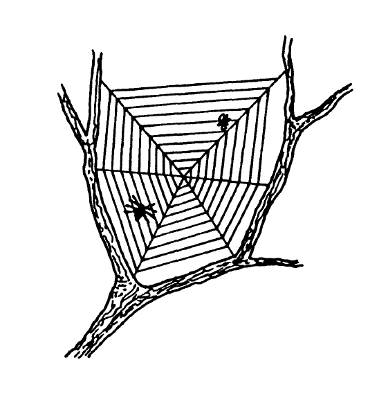
Also in this book we are limited to the consideration of manmade structures. Nature can show us many superbly efficient examples of structures which have evolved to support loads. Some of these are shown in figures 1 .2a-c, and although natural structures can be analysed and investigated using the methods described in this book, we are really interested in the exciting task of creating new structures.
1.3 Analysis
The word analysis is generally taken to mean the process whereby a particular structure with known loads is investigated to determine the distribution of forces throughout the various members that make up that structure. Also it includes determining the distribution of stresses within individual members, which result from the forces imposed on them. Finally, it covers the calculation of deflections (i.e. how far the structure will move) under a particular set of loads. The analysis of a structure is necessary to prove that it is strong enough to support a given set of loads.
Analysis tends to be based on mathematics, and the aim is to get as close as possible to the uniquely correct solution. Analysis is a vital part of the design of safe and cost-effective structures, however, it cannot take place until the basic form of the structure has been decided. We firstly need to settle such questions as ‘should we use steel or concrete?’, ‘How many supports to the beam should we provide?’ These early decisions are referred to as design and not analysis.
1.4 Design
Design is a more difficult word to define than analysis because it means such different things to different people. The term designer is commonly used to describe people who design patterns on carpets, or determine the shape of motor car bodies. Whilst aesthetic design is very important it is not the subject of this book.
Engineering design or structural design, which is the subject of this book, is equally creative -just consider the brilliance of the Forth Railway Bridge or the Golden Gate Suspension Bridge (figure 1.3), two very different solutions to the similar problem of building a long-span bridge over water.
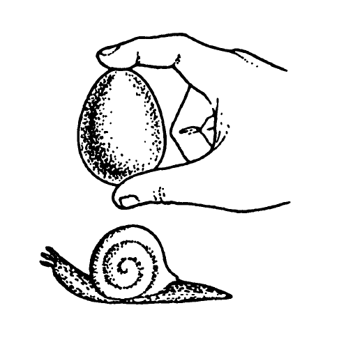
Shells are particularly efficient structures – being rigid and lightweight. The curved surfaces can be very thin
Even within our own field the word ‘design’ can be used in two very different ways. Firstly it is used to describe the whole creative process of finding a safe and efficient solution to an engineering problem. Consider, for example, the above case of designing a bridge across a river. There is of course no ‘correct’ answer, but out of the infinite number of possible solutions, some are clearly much better than others. It is the job of the designer to come up with the best solution within available resources. The design process is dealt with in more detail in the next section.
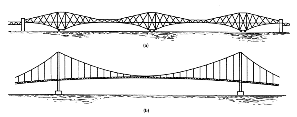
Two brilliant, but very different, solutions to a similar problem
(a) The Forth Railway Bridge, Edinburgh, Scotland, 1890
(b) The Golden Gate Bridge, San Francisco, USA, 1937
The second way that we use the word ‘design’ is in a more restricted sense. It refers to the activities, which often come after the analysis stage, when the forces in each structural member are known. It is the process of determining the actual size of a particular steel column or the number of reinforcing bars in a reinforced concrete beam. This is referred to as element design. Determining the number of bolts in a connection or the length of a weld is called detail design. There may be several choices open to the designer, but element design and detail design are not as creative as the broader design process. They are, however, very important, and bad detail design is a major cause of structural failures.
1.5 The design process
The best way to explain the general approach adopted by a designer in solving an engineering problem is to take ·a simple example- in this case the design of a child’s garden swing. Clearly, with a small project like this, the formal procedure outlined here would not be consciously followed. The designer would simply use his or her judgement to determine the shape of the swing support structure and the size of the members. Nevertheless it illustrates the steps necessary for the successful completion of larger projects.
The usual starting point for a project is a client who has a requirement, and the client will approach the designer, who is often a consulting engineer or architect, and commission him or her to produce a design which satisfies the requirement. The first thing that the designer will request from the client is a clear description of exactly what is wanted. This is called the design brief.
In our case the client is a child who requires a garden swing, and the brief is:
‘Provide, within a period of two weeks, a garden swing, which will be a play facility for many years.’
To arrive at a satisfactory solution the designer will go through the following stages:
- Stage 1 is the site survey and investigation. Suitable locations will be examined and checked to ensure that there are no obstructions within the arc of the swing. Problems of access must be considered and the ground conditions in wet weather taken into account. Finally a few trial-holes might be dug to check that any rock is not too close to the surface to prevent foundations being excavated.
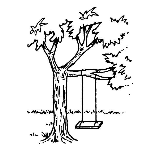
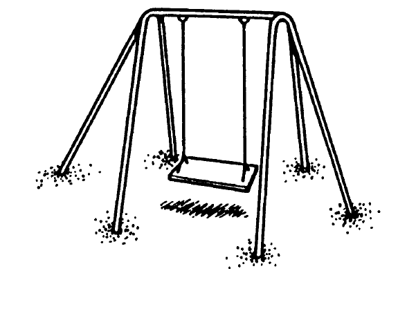
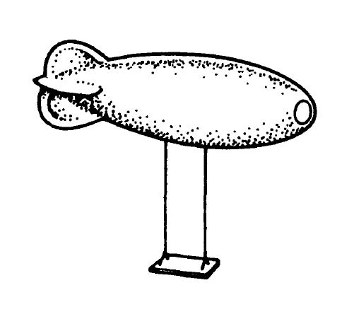
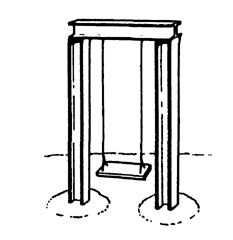
- Stage 2 involves investigating alternative structural concepts. There are an enormous range of structural shapes and materials which could be used and a few of these are shown in figures 1 .4a-f. Each of these must now be evaluated against clear rational criteria in order to select just one or two schemes for further detailed consideration. The type of factors that would be considered in relation to each scheme are as follows:
(a) Fixed to tree. This is the cheapest and best solution, but there is no convenient tree.
(b) A tubular steel frame. They are available from the super-market. Little labour is involved and the swing is mobile.
There are some concerns about cost, durability and appearance, but it is worth bearing in mind.
(c) Suspended from a helium balloon. An interesting solution, but totally impractical.
(d) Welded and bolted steel beams. Very robust but it would have to be prefabricated by a local welder. The result is ex- Figure 1.4f ceedingly ugly and would require painting to prevent rust.
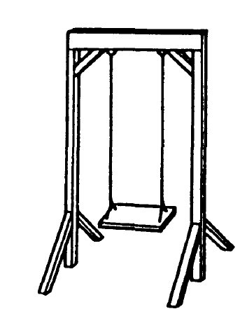
(e) Timber frame with concrete foundations. Good appearance and relatively cheap but high labour content and some maintenance required for good durability.
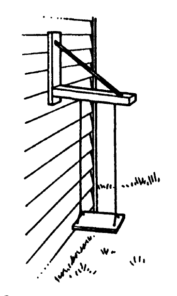
(f) Timber and steel bracket fixed to wall. Unless it is possible to fix the swing away from the comer of the wall there will be safety problems.
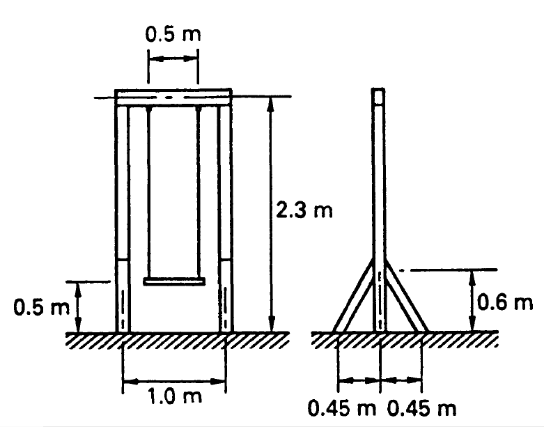
Basic dimensions
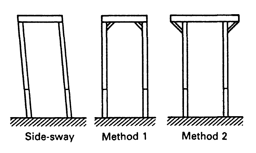
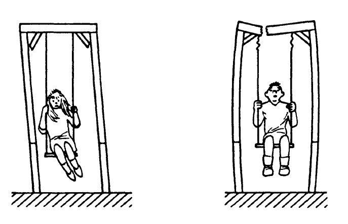
The problem of side-sway and two possible methods of preventing it
The choice therefore comes down to either (b) from the super-market or (e) the timber frame. We will assume that after due
Figure 1.5 investigation of available products the decision is made to go for the timber frame.
- Stage 3 involves more detailed development of the selected scheme. The basic overall dimensions must be decided (figure 1 .5). A method of bracing the frame to prevent side-sway must be found (figure 1 .6). The type of timber to be used will probably be decided at this stage and the range of available sizes investigated.
- Stage 4 is the assessment of loads on the structure. This is not such a staightforward task as you might at first think. The following issues need to be settled.
- Should the swing be designed solely for the weight of a child, or should it be assumed that at some time during its life an adult may use it? I would suggest the latter.
- We need to increase the load by a percentage to allow for the fact that the load is dynamic, i.e. the load is moving, and we must take account of the effects of its inertia. Also the load may be suddenly applied if someone jumps onto the swing.
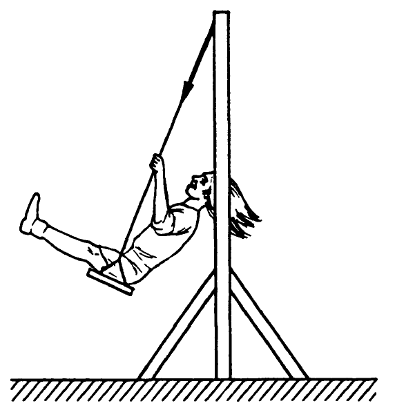
Increasing the static load by, say, I 00% ought to be enough to compensate for these effects. - The load is not always applied vertically downwards.
When the load is inclined, as shown in figure 1 .7, it causes
much more severe bending and overturning problems for the structure. Wind loads often cause severe lateral loads, although they are not much of a problem with thin skeletal structures such as this. - Additional forces result from the actual self-weight of the structural members. With structures such as large bridges these forces are usually much bigger than those that result from the traffic passing over the bridge. These self-weight loads present a problem at this stage of the design process because we do not yet know the final size (and hence weight) of the structural members. The designer must therefore make
intelligent estimates which should be checked later. Obviously, with increased experience the designer gets better at making these estimates. In our case the effect of self-weight will be very small and could be ignored.
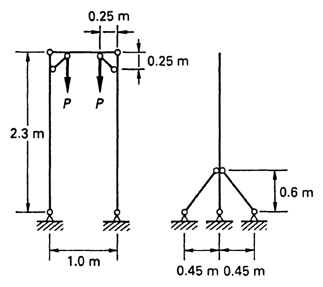
The structural model
Stage 5 is the analysis of the structure. Firstly we must transform the diagram of the proposed structure to obtain a simplified structural model which is amenable to analysis. This chiefly involves classifying the joints between the members as either pinned or continuous. This topic is dealt with in more detail later in the book. Our structural model is shown in figure 1.8.
The loads are now applied to the structural model and the frame analysed to determine the forces and the amount of bending in each member. It may be necessary to carry out The structural model more than one analysis for different load cases. For the swing structure we would probably do it twice – firstly with the load vertical and secondly with the load inclined to produce the worst overturning effect.
• Stage 6 is element design and detail design. Each member must be considered in turn. Taking into account the forces obtained from the analysis, the required size of the member is calculated so that acceptable stresses are not exceeded.
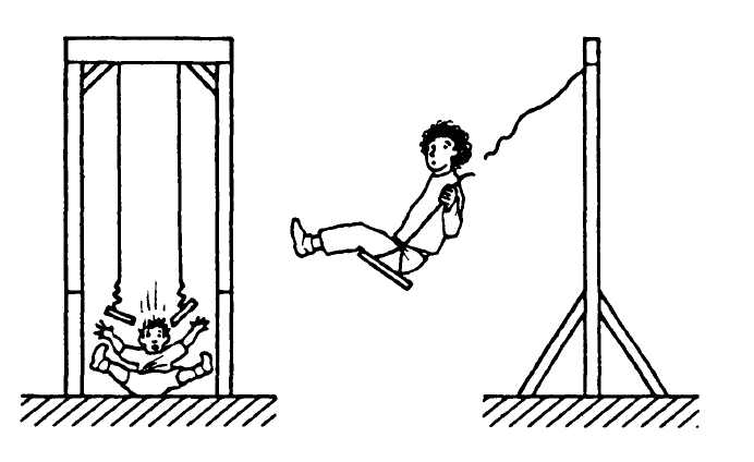
Careful thought must be given to the connections so that forces are adequately transmitted from one member to another. The designer must check all the possible ways in which the structure could fail. Some of these are shown in figure 1.9 and you may be able to think of some others.
Finally, with real structures, the designer must clearly communicate his requirements to the builder by means of detailed drawings and specifications.
Bracing connections fail – Beam breaks
The stages of design are summarised in figure 1.10. It is not always possible to separate the process into such neat steps and often analysis and element design will proceed in parallel. Also the Figure 1.9c analysis to calculate the displacement of the structure can only Bracing connections fail take place after the member sizes are known.
Content
Preface Vll
Symbols IX
Design
2 Basics 17
3 Materials 34
4 Loads 64
5 Pin-jointed trusses 87
6 Tension 115
7 Beams 133
8 Compression 192
9 Combined axial and bending stresses 211
10 Connections 231
11 Arches and portal frames 252
12 Foundations and retaining walls 266
13 Deflection 287
Appendix: Section Properties 301
Further Reading 306
Index